- 您现在的位置:买卖IC网 > Sheet目录334 > ISL8501EVAL1Z (Intersil)EVALUATION BOARD FOR ISL8501
ISL8501
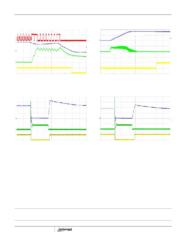
Typical Performance Curves Circuit of Figure 2. V IN = 12V, VIN_LDO1 = VIN_LDO2 = V OUT1 = 3.3V, I OUT1 = 1A, V LDO1 = 1.2V,
I LDO1 = 450mA, V LDO2 = 1.8V, I LDO2 = 450mA, T A = -40°C to +85°C unless otherwise noted.
Typical values are at T A = +25°C. (Continued)
VOUT1 1V/DIV
PHASE 10V/DIV
VOUT1 2V/DIV
IL 2A/DIV
IL 1A/DIV
PG_PWM 5V/DIV
PG_PWM
FIGURE 27. OUTPUT SHORT CIRCUIT, 5μs/DIV
FIGURE 28. OUTPUT SHORT CIRCUIT RECOVERY, 200μs/DIV
LDO2 1V/DIV
LDO1 500mV/DIV
ILDO1 1A/DIV
PG_LDO 5V/DI V
FIGURE 29. LDO1 SHORT CIRCUIT AND RECOVERY,
200μs/DIV
ILDO2 1A/DIV
PG_LDO 5V/DIV
FIGURE 30. LDO2 SHORT CIRCUIT AND RECOVERY,
200μs/DIV
All Intersil U.S. products are manufactured, assembled and tested utilizing ISO9000 quality systems.
Intersil Corporation’s quality certifications can be viewed at www.intersil.com/design/quality
Intersil products are sold by description only. Intersil Corporation reserves the right to make changes in circuit design, software and/or specifications at any time without
notice. Accordingly, the reader is cautioned to verify that data sheets are current before placing orders. Information furnished by Intersil is believed to be accurate and
reliable. However, no responsibility is assumed by Intersil or its subsidiaries for its use; nor for any infringements of patents or other rights of third parties which may result
from its use. No license is granted by implication or otherwise under any patent or patent rights of Intersil or its subsidiaries.
For information regarding Intersil Corporation and its products, see www.intersil.com
12
FN6500.1
July 12, 2007
发布紧急采购,3分钟左右您将得到回复。
相关PDF资料
ISL8510EVAL1Z
EVALUATION BOARD FOR ISL8510
ISL89162FBEBZ
IC MOSFET DRIVER 2CH 6A 8SOIC
ISL89165FBECZ
MOSFET DRIVER 2CH 6A 8SOIC
ISL89168FBEAZ
IC MOSFET DRIVER 2CH 6A 8SOIC
ISL89367FRTAZ
IC MOSFET DRIVER 2CH 6A 16TDFN
ISL89401ABZ
IC DRVR H-BRDG 100V 1.25A 8SOIC
ISL89410IBZ-T13
IC DRVR MOSFET DUAL-CH 8-SOIC
ISL9440AEVAL1Z
EVALUATION BOARD FOR ISL9440
相关代理商/技术参数
ISL8501IRZ
功能描述:电压模式 PWM 控制器 INTEGRTD FETUCK 4X 4 24LD W/ANNEAL RoHS:否 制造商:Texas Instruments 输出端数量:1 拓扑结构:Buck 输出电压:34 V 输出电流: 开关频率: 工作电源电压:4.5 V to 5.5 V 电源电流:600 uA 最大工作温度:+ 125 C 最小工作温度:- 40 C 封装 / 箱体:WSON-8 封装:Reel
ISL8501IRZ-T
功能描述:电压模式 PWM 控制器 INTEGRTD FETUCK 4X 4 24LD W/ANNEAL RoHS:否 制造商:Texas Instruments 输出端数量:1 拓扑结构:Buck 输出电压:34 V 输出电流: 开关频率: 工作电源电压:4.5 V to 5.5 V 电源电流:600 uA 最大工作温度:+ 125 C 最小工作温度:- 40 C 封装 / 箱体:WSON-8 封装:Reel
ISL8502AEVAL1Z
功能描述:EVAL BOARD FOR ISL8502 RoHS:是 类别:编程器,开发系统 >> 评估板 - DC/DC 与 AC/DC(离线)SMPS 系列:- 产品培训模块:Obsolescence Mitigation Program 标准包装:1 系列:True Shutdown™ 主要目的:DC/DC,步升 输出及类型:1,非隔离 功率 - 输出:- 输出电压:- 电流 - 输出:1A 输入电压:2.5 V ~ 5.5 V 稳压器拓扑结构:升压 频率 - 开关:3MHz 板类型:完全填充 已供物品:板 已用 IC / 零件:MAX8969
ISL8502AIRZ
功能描述:IC REG BUCK SYNC ADJ 2A 24QFN RoHS:是 类别:集成电路 (IC) >> PMIC - 稳压器 - DC DC 开关稳压器 系列:- 产品培训模块:Lead (SnPb) Finish for COTS
Obsolescence Mitigation Program 标准包装:2,500 系列:- 类型:降压(降压) 输出类型:两者兼有 输出数:1 输出电压:5V,1 V ~ 10 V 输入电压:3.5 V ~ 28 V PWM 型:电流模式 频率 - 开关:220kHz ~ 1MHz 电流 - 输出:600mA 同步整流器:无 工作温度:-40°C ~ 125°C 安装类型:表面贴装 封装/外壳:16-SSOP(0.154",3.90mm 宽) 包装:带卷 (TR) 供应商设备封装:16-QSOP
ISL8502AIRZ-T
功能描述:IC REG BUCK SYNC ADJ 2A 24QFN RoHS:是 类别:集成电路 (IC) >> PMIC - 稳压器 - DC DC 开关稳压器 系列:- 产品培训模块:Lead (SnPb) Finish for COTS
Obsolescence Mitigation Program 标准包装:2,500 系列:- 类型:降压(降压) 输出类型:两者兼有 输出数:1 输出电压:5V,1 V ~ 10 V 输入电压:3.5 V ~ 28 V PWM 型:电流模式 频率 - 开关:220kHz ~ 1MHz 电流 - 输出:600mA 同步整流器:无 工作温度:-40°C ~ 125°C 安装类型:表面贴装 封装/外壳:16-SSOP(0.154",3.90mm 宽) 包装:带卷 (TR) 供应商设备封装:16-QSOP
ISL8502AIRZ-TR5194
制造商:Intersil Corporation 功能描述:PACHINKO INTEGRATED FET SYNCH BUCK - 4X4 24LD QFN, T&R - Tape and Reel 制造商:Intersil Corporation 功能描述:IC REG BUCK SYNC ADJ 2A 24QFN
ISL8502EVAL1Z
功能描述:EVALUATION BOARD FOR ISL8502 RoHS:是 类别:编程器,开发系统 >> 评估板 - DC/DC 与 AC/DC(离线)SMPS 系列:- 产品培训模块:Obsolescence Mitigation Program 标准包装:1 系列:True Shutdown™ 主要目的:DC/DC,步升 输出及类型:1,非隔离 功率 - 输出:- 输出电压:- 电流 - 输出:1A 输入电压:2.5 V ~ 5.5 V 稳压器拓扑结构:升压 频率 - 开关:3MHz 板类型:完全填充 已供物品:板 已用 IC / 零件:MAX8969
ISL8502IRZ
功能描述:IC REG BUCK SYNC ADJ 2.5A 24QFN RoHS:是 类别:集成电路 (IC) >> PMIC - 稳压器 - DC DC 开关稳压器 系列:- 产品培训模块:Lead (SnPb) Finish for COTS
Obsolescence Mitigation Program 标准包装:2,500 系列:- 类型:降压(降压) 输出类型:两者兼有 输出数:1 输出电压:5V,1 V ~ 10 V 输入电压:3.5 V ~ 28 V PWM 型:电流模式 频率 - 开关:220kHz ~ 1MHz 电流 - 输出:600mA 同步整流器:无 工作温度:-40°C ~ 125°C 安装类型:表面贴装 封装/外壳:16-SSOP(0.154",3.90mm 宽) 包装:带卷 (TR) 供应商设备封装:16-QSOP
